Download This Document
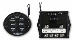
Wireless Control
|
The Wireless control utilizes radio frequency to communicate between the display and trim tab
power module. This design eliminates the need for wiring between the display control and transom
mounted power module. The Wireless combines a microprocessor based trim tab control with an
LED tab position indicator. This control incorporates a convenient "one-touch" button for all tabs
up or all tabs down. Tabs automatically retract and calibrate whenever the control power is
switched on or off. This unique design requires no feedback sensor for tab position. LED indicators
automatically dim at night and brighten in sunlight. The Wireless is completely sealed and waterproof.
Lectrotab's Wireless control is available in single station or dual station.
|
|
|
| FEATURES |
- Utilizes radio frequency for communication between display control and trim tab power module up to 100' (30.5m)
- Convenient "one-touch" button for all tabs up or all tabs down
- Tabs automatically retract and calibrate on key switch on or off
- Easy upgrade from rocker switch control with BP-10 mounting plate
- Completely sealed and waterproof
- Automatically dims LED tab position indicators in darkness and brightens in sunlight
- Adjustable programming features located on back of specification sheet
- Dual stations available
- Operates up to 3 actuators per tab on 12vdc or 4 actuators per tab on 24vdc systems
|
| SPECIFICATIONS |
|
Model Number
|
Display Color
|
Number of Stations
|
Overall Width
|
Overall Height
|
Mounting Hole Cutout (Diameter)
|
DC Voltage
|
WR Power Module Fuse Size (1 Actuator per Tab)
|
WR Power Module Fuse Size (2 Actuators per Tab)
|
WR Power Module Fuse Size (3 Actuators per Tab)
|
WT Supply Power and AUX Fuse Size
|
|
WTR-111
|
Black
|
1
|
3"/76.2mm
|
2.563"/65.1mm
|
2"/51mm
|
12
|
12vdc = 20 amp
|
12vdc = 30 amp
|
12vdc = 40 amp
|
.25 amp
|
|
WTR-121
|
Black
|
2
|
3"/76.2mm
|
2.563"/65.1mm
|
2"/51mm
|
12
|
12vdc = 20 amp
|
12vdc = 30 amp
|
12vdc = 40 amp
|
.25 amp
|
|
WTR-211
|
Black
|
1
|
3"/76.2mm
|
2.563"/65.1mm
|
2"/51mm
|
24
|
24vdc = 10 amp
|
24vdc = 20 amp
|
24vdc = 30 amp
|
.25 amp
|
|
WTR-221
|
Black
|
2
|
3"/76.2mm
|
2.563"/65.1mm
|
2"/51mm
|
24
|
24vdc = 10 amp
|
24vdc = 20 amp
|
24vdc = 30 amp
|
.25 amp
|
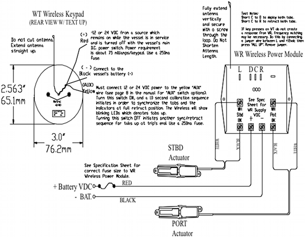
| WIRELESS WIRING/INSTALLATION DIAGRAM |
| WIRELESS PROGRAMMING |
|
|
Program Mode Sequence
|
|
|
Function
|
Enter
|
Adjust
|
Exit
|
Range
|
Default
|
Program Details
|
|
Timing
|
PORT BOW DOWN
|
STBD BOW DOWN/UP
|
PORT BOW UP
|
4 - 12sec
|
8sec
|
8 LED's = 8 second actuator
4 LED's = 4 second actuator
|
|
LED's On/Off
|
ALL DOWN
|
ALL UP
|
PORT BOW UP
|
On/Off
|
On
|
All LED's flashing = LEDs ON
1 LED on each = LED's OFF
|
|
Swap LED's
|
ALL UP
|
ALL UP
|
PORT BOW UP
|
LED's Opposite of button/same side button
|
LED's Opposite of button press
|
8 LEDs on right side = LED lights opposite of button press
8 LEDs on left side = LED lights same side as button press
|
Enter, Adjust and Exit Program Mode:
- Before entering program mode, 12vdc or 24vdc must be applied to Wireless (WT) main power
- Power to AUX (Yellow Wire) must be OFF (Aux is typically connected to ignition key switch or aux switch)
- Press and hold button noted in Wireless Programming chart under column "Enter" for more than 2 seconds while switching the Aux terminal switch to ON at the same time
- Release the "Enter" button and press button in "Adjust" column to change the value
- Press and hold "PORT BOW UP" for more than 2 seconds to exit program mode